
Documentation
3D Views
Prepare GLB models, map meshes, save cameras, and place artwork reliably on complex surfaces.
Three-dimensional views use Babylon.js. The renderer is loaded only when a 3D view is needed, so a 2D-only storefront does not download Babylon.
Who this is for
3D product administrators and model preparation teams
What you will achieve
A correctly oriented GLB scene with mapped parts, stable cameras, synchronized variations, and surface-aware customer artwork.
Before you begin
- A valid GLB file.
- Meaningful mesh names.
- Permission to upload GLB files in WordPress.
- A WebGL2-capable browser for testing.
Prepare the GLB before upload
Model quality determines runtime quality. Correct unnecessary fragmentation, scale, orientation, and material naming before treating the file as a product.
- Use a consistent real-world scale and a centered origin.
- Apply Blender transforms before export.
- Keep meshes separate only when they need distinct material, variation, selection, or drawing-area behavior.
- Use readable mesh and material names.
- Remove hidden geometry, unused materials, oversized textures, and unnecessary animation.
- Export normals and UVs correctly.
Tip: The premium GLB optimizer can help prepare a model, but it cannot infer your product semantics or correct every modeling decision.
Upload and create the 3D view
Where to go: Product builder > Views > Create 3D view
After the view is created, wait for the Babylon bundle and model to finish loading before adding objects or invoking 3D tools.
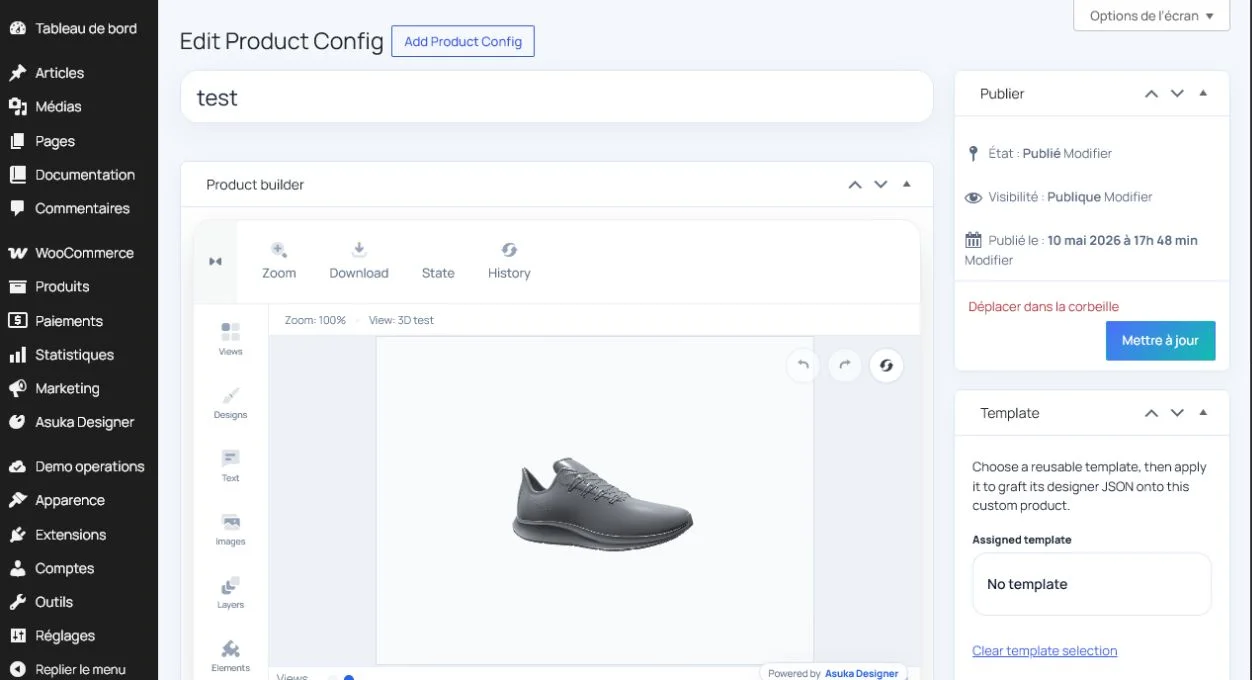
- Select the GLB from the media library or upload it.
- Wait until the scene is visible and the view reports ready.
- Confirm camera drag directions feel natural.
- Check that the entire product fits the initial frame.
- Save before configuring detailed behavior.
Avoid this: “The render engine addon is not loaded yet” means an operation ran before the 3D view-ready state. Do not retry object creation until the scene is ready.
Map meshes to product elements
Mesh mapping connects geometry to the shared product model.
- Group meshes that represent the same logical product part.
- Map independently configurable meshes to separate elements.
- Attach material and color variations to the correct element.
- Select the mesh in the scene and verify the Variations module opens the matching element.
- Switch repeatedly between two elements to ensure selection does not jump back to a previous root.
Configure materials and variations
Where to go: Materials, Elements, and Variations modules
A visual material change should modify only the intended mesh set and remain synchronized with related 2D or 3D views.
- Use stable variation IDs across views.
- Keep display labels independent from machine IDs.
- Test color, texture, visibility, and material-property changes.
- Confirm switching a Handle variation does not select or recolor Body.
- Return to the variation root and verify the camera returns to the product center.
Save root and focused camera states
Where to go: Camera module
The root camera frames the entire scene. Focused cameras make a selected product part easier to inspect.
- Frame the complete product and save the root camera.
- For a single product, prefer rotating around the existing target rather than moving the product in space.
- For scenes containing several products, move the camera target only enough to frame the selected element.
- Save configured focused views when automatic framing is not satisfactory.
- Return to the root and confirm the camera recenters predictably.
Create 3D drawing areas and markers
A 3D area may be a whole mesh or a drawn region on its surface. A marker is an insertion target that can later be replaced by customer content.
- Select the intended mesh before creating a mesh drawing area.
- Use a drawn surface region when only part of the mesh is printable.
- Attach added layers to one selected area when several areas exist.
- Center markers on the clicked surface point.
- Align inserted and dragged content to the local surface tangent and normal.
Validate surface placement and occlusion
Artwork should be reconstructed from the permitted surface, not projected as a camera-facing rectangle.
- Drag from front, side, rear, and oblique camera angles.
- Test near and far zoom levels.
- Cross mesh boundaries and verify the layer stays clipped to the assigned area.
- Rotate the camera after placement and confirm artwork is not visible on unrelated meshes or through the opposite side.
- Compare the live drag preview with the committed result after pointer release.
- Test text and asymmetric images to detect horizontal or vertical mirroring.
Success check: The same placement remains correctly oriented, clipped, and occluded from every camera angle.
Optimize performance
- Reduce unnecessary meshes and material slots.
- Compress textures to appropriate dimensions.
- Avoid rebuilding expensive surface patches more often than the drag workflow requires.
- Test a realistic number of customer layers.
- Monitor memory during repeated view changes and long sessions.
- Use the GLB optimizer only when licensed and include the generated add-on chunk in the deployment.
Need to verify the result?
Run Asuka Designer > QA & Diagnostics, then repeat the customer workflow in a private browser window.