
Documentation
Drawing Areas and Markers
Constrain customer content to printable regions and create guided insertion points.
Drawing areas define where content is allowed. Markers define where a new object should be inserted or which placeholder it should replace. They solve different problems and may be used together.
Who this is for
Product and production administrators
What you will achieve
Every customer layer belongs to an explicit printable area and markers insert replacement content at the correct point and orientation.
Before you begin
- The product views are already configured.
- The printable regions and physical dimensions are known.
- Drawing Areas and Marker entitlements are active when those premium modules are used.
Understand the difference
- Drawing area: a boundary and measurement reference that can constrain many layers.
- Marker: a fixed slot or insertion point that can be replaced by text, image, design, or another supported object.
- Mesh drawing area: a complete 3D mesh used as the permitted surface.
- Drawn 3D area: a smaller region defined on a mesh surface.
Create a 2D drawing area
Where to go: Drawing Areas module on a 2D view
- Create the area and position it over the printable region.
- Give it a customer-friendly name.
- Set width and height in the real production unit.
- Choose the containment behavior.
- Save, reload, and test all four edges with a large layer.
Create a 3D drawing area
Where to go: Select a mesh, then open Drawing Areas
- Use the complete mesh when every visible part of it is printable.
- Draw a smaller surface region when the mesh contains non-printable areas.
- Confirm unrelated meshes are excluded even when they sit in front of or behind the selected mesh.
- Rotate the camera and verify the clipped layer remains stable.
Avoid this: A camera-facing clipping rectangle is not a valid 3D drawing area. The final patch must be constructed from the selected surface triangles.
Assign layers when several areas exist
The customer must know which area receives a new layer.
- Give each area a distinct label.
- Present the area choice before or immediately after object insertion.
- Store the chosen area ID on the layer.
- When the layer is selected later, show only its attached area for context.
- Keep the layer inside that area during live drag, not only after release.
Create and replace a marker
Where to go: Marker module
- Click the intended center point.
- Confirm the marker center matches the pointer position.
- Set the replacement types and behavior.
- Replace the marker with an asymmetric test image or readable text.
- Move the resulting layer and verify it follows the same area and surface rules.
Tip: Use readable text such as “FRONT” and an asymmetric image during testing. Mirroring and rotation errors become immediately visible.
Customer permissions
Viewing and using configured areas is different from authoring them.
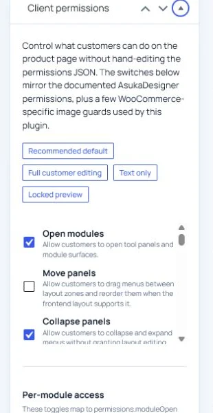
- Allow customers to view drawing areas when they need placement guidance.
- Keep create, edit, and delete drawing-area permissions disabled unless customers are intentionally authoring regions.
- Use the same rule for marker create, edit, and delete permissions.
- Ensure the assigned template includes the modules or contextual actions customers actually need.
Need to verify the result?
Run Asuka Designer > QA & Diagnostics, then repeat the customer workflow in a private browser window.